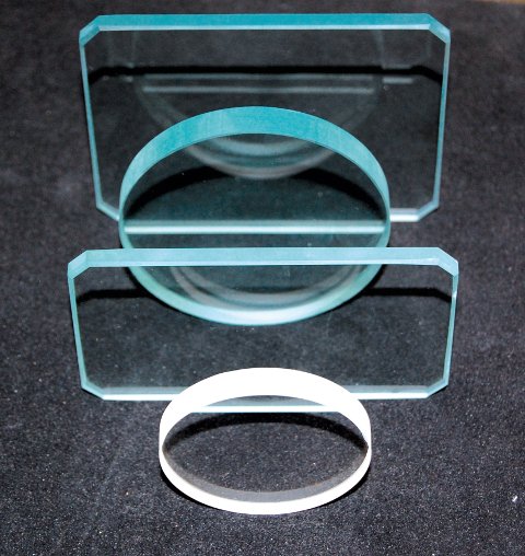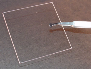
In most cases the optical axis of the retardation material is confined to the surface plane of the anisotropic plate. Compensators and retardation plates have varying anisotropic plate thickness and optical properties targeted at producing a specific optical path length difference or relative retardation between mutually perpendicular (orthogonal) plane-polarized light waves when inserted diagonally in the microscope between crossed polarizers. More recently, several manufacturers have shifted to the application of a highly aligned and stretched linear organic polymer to produce anisotropic retardation plates.
#QUARTZ ZERO BACKGROUND PLATES WINDOWS#
Retardation plates are composed of optically anisotropic quartz, mica, and gypsum minerals ground to a precise thickness and mounted between two optical windows having flat (plane) faces, which are designed to introduce a fixed amount of retardation between the orthogonal wavefronts passing through the crystal. Furthermore, if either the birefringence or the thickness of a specimen is known, the other parameter can be easily determined. From this relationship, it is obvious that specimens having differing thickness and refractive index gradients can display identical optical path differences or relative retardations. The terms (refractive index and thickness) on the right side of the equation are collective referred to as the specimen birefringence. Where t refers to the thickness of the specimen (the physical distance traversed by light waves through the specimen), n(e) is the refractive index experienced by the extraordinary wavefront, and n(o) is the refractive index experienced by the ordinary wavefront.

The terms relative retardation, used extensively in polarized light microscopy, and optical path difference ( D or OPD), are both formally defined as the relative phase shift between the orthogonal wavefronts, expressed in nanometers, according to the equation: D = G = t Addition of a retardation plate or compensator to the polarized light microscope produces a highly accurate analytical instrument that can be employed to determine the relative retardation (often symbolized by the Greek letter G) or optical path difference between the orthogonal wavefronts (termed ordinary and extraordinary) that are introduced into the optical system by specimen birefringence. Optical anisotropy is studied in the polarized light microscope with accessory plates that are divided into two primary categories: retardation plates that have a fixed optical path difference and compensators, which have variable optical path lengths. Quantitative measurements of optical anisotropy is therefore useful in the optical analysis of birefringent specimens. When the ordered state involves structural anisotropy, the optical state usually also displays anisotropic effects in polarized light observations. In many cases, molecular ordering in these specimens is an intrinsic material property, but order can also be induced on multiple levels by dynamic shear, stretching, concentration changes, temperature fluctuations, and force fields.

Polarized light microscopy is a valuable tool for revealing the presence and nature of submicroscopic structural motifs in a wide variety of materials ranging from mineral thin sections to fibers and biological specimens.

Polarized Light Microscopy Introduction to Compensators and Retardation Plates

Molecular Expressions Microscopy Primer: Specialized Microscopy Techniques - Polarized Light Microscopy - Introduction to Compensators and Retardation Plates


 0 kommentar(er)
